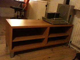
Today I put two Bestas together. It is the simplest piece of IKEA furniture I have seen so far. I wanted two, one to put my TV on and one to put my printer on.

It comes in one box only. Easy peasy.

There is of course the standard IKEA Allen key included but I had no use for it. I did need these guys though; a flat screw driver and a Phillips screw driver.

Start by screwing these guys in the top piece. You need six.

Then place the sides and fix them.

The short ones are used for the sides, the long ones are for the thicker middle part.

Sides and middle part attached.

Slide in the back pieces.

Then screw the remaining six fixation points in to the bottom part (recognisable by the extra, smaller holes)

Turn the cupboard on its side.

To mount the bottom piece, place it next to the cupboard and fix one side first.

Then fix the remaining points.

The Besta standard comes with these little feet.

I bought the higher legs for it though.

They are easy to attach. (And you will get 4 Allen keys of the same size...)

And there it is.

The cupboard in place.
 Today I put two Bestas together. It is the simplest piece of IKEA furniture I have seen so far. I wanted two, one to put my TV on and one to put my printer on.
 It comes in one box only. Easy peasy.
 There is of course the standard IKEA Allen key included but I had no use for it. I did need these guys though; a flat screw driver and a Phillips screw driver.
 Start by screwing these guys in the top piece. You need six.
 Then place the sides and fix them.
 The short ones are used for the sides, the long ones are for the thicker middle part.
 Sides and middle part attached.
 Slide in the back pieces.
 Then screw the remaining six fixation points in to the bottom part (recognisable by the extra, smaller holes)
 Turn the cupboard on its side.
 To mount the bottom piece, place it next to the cupboard and fix one side first.
 Then fix the remaining points.
 The Besta standard comes with these little feet.
 I bought the higher legs for it though.
 They are easy to attach. (And you will get 4 Allen keys of the same size...)
 And there it is.
 The cupboard in place.


