Wednesday, December 24, 2008

Installing Windows from USB on the Asus Eee pc 1000H

As a new owner of an Asus Eee pc 1000H one of the first things I wanted was to install Windows XP my self. I didn't like how it had loads of stuff pre-installed. But because the device does not have an optical drive the only external device I could boot it from was a USB stick. I never created a bootable USB stick and getting the Eee pc to boot from it was not easy either. Then there is the issue of Asus only providing an image of the factory installed system so that you can really only get it back to the factory 'cluttered' default state. You can not do a clean install from that dvd.

But there are tricks. Tricks that allow you to start a proper Windows XP installation from a USB stick. A Windows XP installation that was created from the factory installed Windows XP on your Eee pc. I'll outline everything in this blog post.

Disclaimer
Everything described in this post worked for an "out of the box" Eee pc 1000H (with finished setup) using a 4GB Kingston DataTraveler USB stick (slider version).

Performing the above actions CAN result in failure with your computer's harddrive being wiped withough having a working installation of Windows on it.

Entering the BIOS.
First things first. It's hard to enter the BIOS of the Eee pc. To make it easier, once you manage to get in by keeping the F2 key pressed whilst booting, find the "Boot Booster" setting and disable it. This will make the booting a bit slower but it will allow you to enter the BIOS or the boot menu a lot easier. Which brings me to the next issue.

The Boot menu.
The Eee pc can boot from USB devices such as USB sticks or optical USB connected devices. Even though you can set the boot order in the BIOS to look for a USB device first, it never worked for me. But then I found out that pressing ESC while booting takes you to the boot menu where you can select any connected USB device.

Creating a bootable USB stick that starts the Windows XP setup.
First off you need to download some Windows 98 DOS files here and unzip them in a directory anywhere. Also, just incase, download the USB Disk Storage Format Tool here.

Now you need to install a little tool called WinSetupFromUSB on your Eee pc. This tool will use your existing Windows installation to create setup files with. You can download it from here and you find more info on it here. After installing you can run it from the Windows Start menu and this is what it looks like:

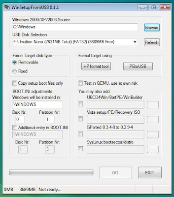
With the top-most Browse button, locate the folder that has the I386 folder in it and select that folder. With the second Browse button, select your USB stick.

If you haven't prepared your USB stick yet, click the HP Format Tool button. This will start the USB Disk Storage Format Tool from Hewlett-Packard. You may need to install this previously.

The USB Disk Storage Format Tool has the following interface:

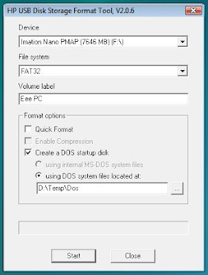
After setting the interface's properties like above, hit the Start button. It will create a Windows 98, DOS-mode bootable USB stick.

When this is finished, you return to the WinSetupFromUSB screen. When you hit the Go button it will start creating a Windows XP setup on the USB stick for you. This may take a while. Maybe go watch some Family guy episodes or something.

Installing Windows XP
When the setup is created and you reboot your machine, keep the ESC key pressed to select your USB stick to boot from.
Select the first part of the setup. This will start the text based part of the Windows XP setup. After a reboot (leave the USB stick) press ESC again to boot from the USB stick and this time select the second setup-stage which is the GUI part.
If you forget to press ESC the Eee-pc will boot from the hard disk and complain it can't find the file HAL.DLL.

From here onwards you just follow the Windows XP setup.

When Windows is installed you will need to install all the drivers manually. You can find those in the Drivers directory on the Asus provided dvd. Copy them on a USB stick and install them one by one.

Saturday, September 20, 2008

Finishing the drawers

OK, it's taken a while but you know, I'm a busy guy...

To finally finish the drawers, all that needed to be done was putting on a nice front and knob. The fronts I made from plywood panels, 4 mm thick. The knobs I bought at the hardware store.

I measured the size quite precise. Then the panels were cut and glued on to the drawers. Use a glue that dries fast so that you don't have to keep it pressed for hours. You wouldn't enjoy that, trust me.

In the picture you can see that I stuck a little piece of paper in between two panels. Like wise I also had one stuck under the bottom drawers at some point. This is to make sure the panel doesn't move down. You know, gravity and such.

After they dried I drilled a hole in the front where the knob would come. Screw the knob on and it's done.

Finally this project gets the status "closed".

A simple monitor stand

When you are looking at a computer screen eight hours a day, it is important to have them at a correct height otherwise you will screw up a few muscles here and there. Mine seem to get a bit unhappy at the moment so I made this monitor stand to elevate my screens. Another benefit is that you will be able to put the keyboard underneath it, creating room for papers and books etc.

Introduction: Meet Ms. table leg and Mr. shelf.

The table leg can (in my case) be screwed apart. That way we have the leg and the leg-plate. "Leg-plate" is probably not the correct name but I don't know what is. If you do, please let me know.

Use the leg-plate to draw circles where it will be screwed on the wood.

After drilling the holes (make sure NOT to drill all the way through!), mount the leg-plates on the wood.

When all leg-plates have been screwed on the wood, screw on the table legs.

And there she is, a beautiful, simple but elegant, monitor stand.

Sunday, August 31, 2008

Making a drill press stand

A while ago I found a drill press in our shed, wrapped in plastic. It didn't have a stand or anything though so I put it on the work bench. Recently, a frame became available after the bird cage that it was supporting was seriously upgraded. I quickly put the pieces of this simple puzzle together and hence this blog gets a new entry!

So there were a drill press and a frame. I also found a piece of 4 cm thick wood. Just chipboard but really strong. It had a workable size already, I didn't even have to cut it. How convenient is that?

These are the only things I had to buy: 6 angle brackets and 2 M10 nuts and bolts.

Use the 6 angle brackets to firmly mount the wood to the frame and you end up with a table.

Then use the M10 nuts and bolts to fix the drill press on to the table and you have a nice drill press stand.

Saturday, August 23, 2008

Creating a bird cage roof

We got two new bird cages for outside but they don't come with a roof. So we make some ourselves! The roofs are made out of scrap wood except for the panels. I reckon you may have some panels lying around as well though.

The roof is a simple, 90 degree model. Start by making the legs for the frame. Cut one side at a 45 degree angle. You need 4 per roof.

A fancy connection is not required so just put pairs in a vice, drill a hole for the screw and screw the two parts together.

The result should look like this.

Add a few more pieces of scrap wood like in this photo and you got your frame.

Put the panels on. Don't worry if your frame is a bit wobbly. After the panels have been screwed on it will be completely steady.

Paint.

And place on top of the cage.

Sunday, August 3, 2008

power supply (now 0.75-30V / 2.7A), part 5.

One last part is needed to put the wires together. Just incase it needed to be taken apart (maybe because things can screw up sometimes? ;-P ) I wanted to be able to de-solder the wires leading to the heat sink from the print board. Therefore I cut out a piece of plexi-glass (I cut a semicircle), drilled some holes in it and mounted solder lugs on them. One for each wire to be connected. After this it was testing time (basically a check to see if nothing explodes ;-).

The piece of plexi-glass is at the front here. Click the picture for a slightly larger, but much clearer version.

The finished back.

The finished front.

Finished from above.

Project completed successfully!

Sunday, July 27, 2008

Power supply (now 0.75-30V / 2.7A), part 4.

Mounting the transistors on the heat sink is a yucky job. You have to put paste in between the transistors and the heat sink to help conducting the heat. I used one with silver in it, it conducts heat better. Unfortunately , because of the silver it also conducts electricity better.

I first put a thin layer of paste on the heat sink. And thin means THIN. It's only purpose is to fill up microscopic holes to flatten the surface more for better contact.

Then I put the mica insulating washers in place. I actually made the holes for the transistor pins a lot bigger because I don't want the pins to come in contact with the paste due to the paste's electrical conductivity.

After this I put another very thin layer of paste on the bottom of the transistor and placed them on top of the mica washer.

After this the transistors have to be screwed on to the heat sink. The casing of the transistor will actually carry 34 Volts but I didn't want to put 34 volts on the whole heat sink, hence the mica washers. One of the screws was isolated from the transistor and is simple to use. The other one was in contact with the transistor because it will serve as the +34V contact of the transistor. It therefore is screwed directly on the transistor and the screw is shielded from the heat sink by little plastic cylinders inside the hole in the heat sink. Put a solder lug on it and fix it.

The end result of today's DIY.

PS: A note on the mica washers. The ones you buy can be pretty thick, some times more than 0.25 mm. This influences the thermal conductivity, you want them to be thinner. With a sharp knife and some patience you can "slice" them in thinner ones. The one I bought were 0.1 mm and I sliced them in half.

Tuesday, July 22, 2008

Power supply (now 0.75-30V / 2.7A), part 3.

The power supply does need a fair bit of heat sink. Possibly later on a fan will need to be mounted but I'm not doing that yet.

To work with chunky metal it's handy to be able to use a drill press. It's very stable and it's also safer then drilling from the hand.

I had the vice screwed to the table. This was to prevent it from being lifted while drilling which could cause danger. The holes for the transistors are 4 mm wide. The four outer holes were drilled with a 4.5 mm drill to make M5 screw thread in them. I think actually you need to drill an even smaller hole for M5...

After the holes are drilled, the four outer ones needed to get screw thread in them.

Et voilá, the heat sink with beautiful holes in it, ready to be used.

Sunday, July 20, 2008

Power supply (now 0.75-30V / 2.7A), part 2.

The past few weeks I have redesigned the circuitry a few times and this is the "latest and greatest". Also I have bought a new transformer with 2x12V coils. Because of this I can use less power when using a lower voltage. This is good because it makes the transistors less hot. The power supply will have two voltage ranges: 0.75 - 7V and 5.5 - 30V. The maximum current will be around 2.7A

The new schematics. Click picture for a larger version.

The board with it's components. A heat sink may be added here and there in a later stage.

This is the power supply close to it's current phase. At the moment the board is connected to all front-side controls. The transformer is wired too. Now the board needs to be hooked up to the transformer and the transistors need to be mounted on the heat sink and wired. That will be done soon.

Monday, June 9, 2008

Re-using an old wheel barrow

A couple of weeks ago I found this old wheel barrow in the back of the garden. I thought it was a shame to let it go to waste so I thought I fix it up a little bit.

The frame was really rusty and needed sanding. The worst part of the job...

Then I painted the frame blue. I used some paint that is OK for covering sanded rusty surfaces.

To be able to use the wheel barrow again (decoratively) I made a wooden tray and gave the wood several layers of varnish. The last layer was a nice glossy one.

I think it looks nice and I'm happy to have used the wheel barrow instead of letting it go to waste!

Replacing an outside light

We had this outside light that we wanted to replace with a sensor light so that it would turn on automatically. The new light was bought at the DIY store and has both a light and a sensor.

Before starting I checked for 3 important things:
1) Is there enough room to mount the new light?
2) Will there be enough cable to reach IN to the new light?
3) Has the power been turned off?

You really don't want to find out the answer to any of these questions is "no" after you started...

This is the old light. Say "bye bye" now.

Unscrewing was a bit of a struggle. When screws seem fixed by rust or other crap, just give the case a few whacks with a hammer to loosen things up a bit. It did the trick for me :-)

After removing the old light, I cleaned up and tidied the wires. Work gets a lot easier and nicer when you have a clean and proper workplace.

Then I mounted the back panel of the new light and I connected the mains wires.

Next I connected the wires coming from the sensor and the light.

Screw the front on the back and you're done.

Friday, May 23, 2008

New track lay-out

To be able to use the spirals the trains need to drive upwards with the smallest slope possible. This is the outside track. This meant the spirals had to be on the other side which is changed in this lay-out.

Sunday, May 18, 2008

Test spiral

Mainly to see how this is really done but also to test what some "authorities" in model railroad building are saying, I build a small test spiral this weekend. Before anything else I must say that this spiral will only be used by trains consisting of max. 5 cars including a locomotive.

It's N-scale. The curves are R1 and R2 and there are 5 cm's between levels. The outer track has an incline of 3.8% and the inner track has an incline of about 4.5% (which is why we drive up along the outside as that has the smallest incline).
The spiral was made from 3 mm thick MDF panels. This is really thin but surprisingly stiff when fixed properly!

During this build, a few things went wrong which is good so I won't do it again when building the real thing later.

Start with cutting the biggest pieces of wood. I was going to try several kinds of wood but the 3 mm MDF worked so well that I didn't bother trying the others. The white panel is 18 mm thick melamine crap wood.

I made a giant compass to draw all the circles required to build the spiral on the white panel. After you draw the circles, mark the points where a rod is going to be.

To fix the different levels, get some threaded steel rod. Make sure it's nice and smooth and clean thread. I had to go back to buy new ones. After I cut the first ones up I noticed how crap they were and that you couldn't put a nut on it without using heavy machinery...

Mount all the cut rods firmly.

Because the edge of a panel is in the middle of a circle you can't position the compass properly. I made a little helper out of scrap wood.

Place one panel tight against the helper and draw your circles on the panel. As the spiral goes up, the diameter of the circles should be a little bit bigger than what you drew on the white panel. The formula for this is the Pythagoras formula: A^2 = B^2 + C^2. So if the diameter of the outside of the spiral track is 50 and it goes up 2.5 cm (!!! HALF of the spiral distance of 5 cm in my case !!!) you should use a diameter of sqr(2500 + 6.25) = 50.1. This may look too little to bother with but it works a lot nicer when things fall in place well instead of forced.

If all goes well you end up with a lot of circles. Inside and outside of the spiral and circles for rod positions.

When that's done, cut out the half tracks.

Now the best part can begin: Building the actual spiral. Fix the spiral track on the rods between 2 nuts. I had to fix the bottom with a nail because it wouldn't go down. Possibly due to a miscalculation (I used the whole 5 cm instead of 2.5 cm when calculating new diameters...)

Build the spiral further.

spiral tracks may have to be fixed to each other to make them even.

Do bit by bit, including the track because you can't really reach well.

And when it's finished, test it by running a train up and down. Here's my little NS 1100 pulling a few cars without any trouble.

Here my NS 1200 pulls 3 cars up the spiral without much effort.

I have to say though, my little glasskasten has a lot more trouble going up the hill.